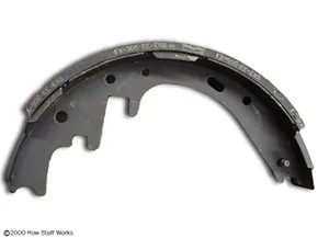
Most drum brake service comes down to one thing: replacing the brake shoes. It’s the bread and butter of drum care. You can often peek inside the back of the assembly through a small inspection port. It gives you a quick read on how much lining is left. If you see rivets, the rule is strict. Replace the shoes when the friction material hits a 1/32-inch (0.8 mm) limit from the hardware. Some modern shoes are bonded directly to the backing plate. No rivets there. In those cases, you have a bit more wiggle room. Keep them until only 1/16-inch (1.6 mm) of material remains.
Long-term neglect changes the game. If you run a shoe down to its metal bones, the exposed rivets act like chisels. They carve deep scores into the drum’s inner surface. Once that happens, you have a choice. You can try to machine the drum back to spec. Or you can replace it entirely.
This is where drum logic flips the script on disc brakes. With rotors, you are always worried about minimum thickness. Run it too thin, it warps or cracks. Drums work differently. They have a maximum allowable diameter. The friction happens on the inside. As you cut material away to smooth out the grooves, the diameter expands. You aren’t getting smaller. You are getting bigger. There is a hard limit on how far you can stretch that circle before the brake doesn’t seal properly or the hardware fails. Stay within those specs or the job isn’t done.
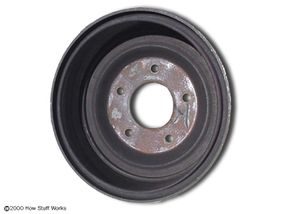
The anatomy of drum brakes isn’t just about friction; it’s about geometry and leverage working in unison. If you want to see exactly how the shoe, cylinder, and adjuster interact under load, the visual breakdown on the next page is where you need to look.
Behind the Drum
Once you peel back the steel or aluminum cover, you’re looking at a system that has changed very little in a century. The core components are the brake shoes, which are lined with friction material, and the wheel cylinder that pushes them outward.
“The simplicity of drum brakes is their greatest strength, but also their Achilles’ heel when it comes to heat dissipation.”
On the front axle, these systems are often paired with disc brakes, serving as the parking brake mechanism. The rear drums, however, handle the bulk of the stopping power in many budget-oriented or older performance vehicles. The self-adjusting mechanism, usually a star wheel and lever, takes up slack as the linings wear down. It’s a passive system. It doesn’t need input. It just reacts.
Why the Diagram Matters
Understanding the layout helps when you’re diagnosing a spongy pedal or uneven wear. The primary keyword for this breakdown is how drum brake components function. Knowing which part does what allows for quicker repairs and better maintenance habits.
Secondary queries often revolve around:
– How to replace rear drum brake shoes
– Difference between front and rear drum brakes
– Drum brake adjuster location
– Signs of failing wheel cylinder
The illustration on the following page details these parts clearly. It shows the anchor pin, the return springs, and the adjuster screw. These are the small things that make the system work or fail. Without the right pressure, the shoes don’t contact the drum evenly. Without the right spring tension, they don’t retract. Dragging brakes are a common symptom of a missed step in this process.
Visualizing the Mechanics
The next page provides a cutaway view. This is crucial for seeing the internal clearance. You can trace the hydraulic line from the master cylinder to the wheel cylinder. You can see the brake shoe backing plate bolted to the axle housing or subframe. It’s a rigid setup. There’s no flex here. That’s why they’re durable. That’s also why they fade under heavy use. Heat builds up inside the drum. It has nowhere to go.
This is the final piece of the puzzle. The detailed illustration completes the picture. Check the next page to see it all laid out.